


Last updated: March 28, 2009 | Contact Webmaster | © 2010 CHR-CSM

LOGIN REQUIRED:


RESEARCH AREAS:
CENTER FACILITIES
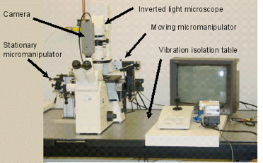
The micro-mechanical force apparatus was designed by Dr. K. T. Miller in 2002, and brought over to the laboratory from the Colorado School of Mines Material Science department in 2004. The micro-mechanical testing apparatus was developed to measure the adhesive forces acting between hydrate particles submerged in a cooled liquid. As shown in the figure, an inverted light microscope (Carl Zeiss Axiovert S100) is positioned on a vibration isolation table. A cooling cell is attached to the microscope stage, in which hydrates are submerged in a cooled liquid. Two micro-manipulators are connected to the microscope to control the movement of the hydrate particles. One manipulator is a relatively low precision hand-operated micro-manipulator (Narishige MN-151) which is held stationary during the experiment. A second, high precision remote-operated micro-manipulator (Eppendorf Patchman 5173) is used to move one of the hydrate particles.
Digital video microscopy is used to track the movement of particles attached to low spring constant cantilever beams, as the beams are displaced with the moving micro-manipulator. The cantilever beams are made of thin glass fibers (~30 µm diameter) and are attached to the inside of the capillary tubes by epoxy cement. The capillary tubes are held in place by cantilever holders attached to the micro-manipulators. The micro-mechanical force measurement technique is illustrated schematically in the figure below. Hydrate particles are formed on the end of thin glass fiber cantilever beams, which act as springs. Using the micro-manipulators, the hydrate particles are brought into contact (A). Using the remote operated manipulator, a preload contact force of ~10 µN is applied to the hydrates particles and held stationary for multiple seconds (B). The particles are then gently pulled apart from each other using the remote operated manipulator. While the particles are being pulled apart, the stationary cantilever bends due to the particle-particle adhesion (C). At some critical displacement, the adhesive bond between the particles breaks, and the particles separate (D). This displacement of the particles is tracked using digital video microscopy and image analysis. For each adhesion force measurement, the particles are pulled apart 40 times to obtain a range of forces.
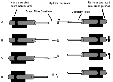
(A) Resting position. (B) Initial preload. (C) Maximum displacement immediately prior to pulloff. (D) Equilibrium cantilever position after hydrates separated.